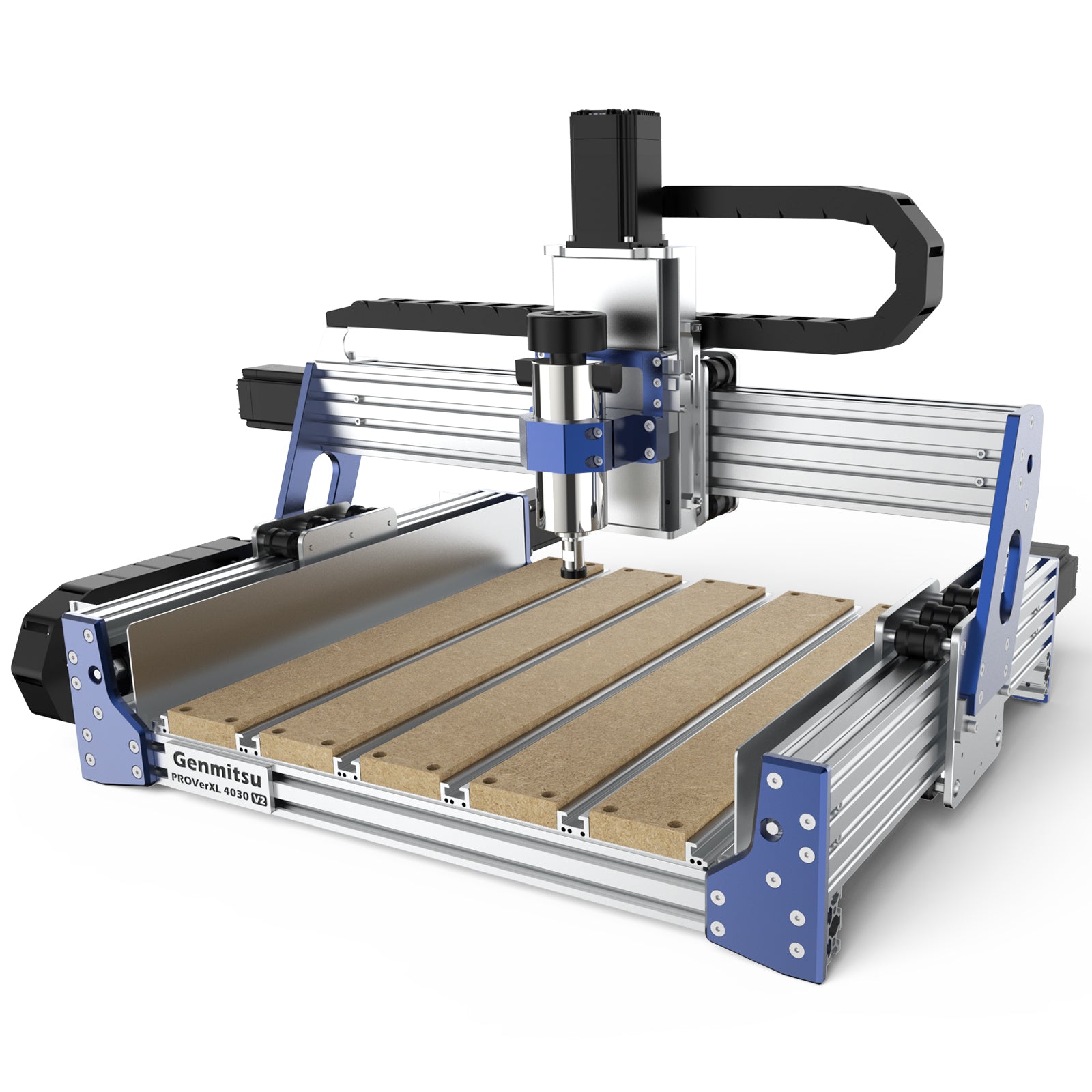
CNC Wasteboard — Design, Materials, and Why Surfacing First
A new machine's bed and spoilboard may not sit at a constant height relative to the cutter. Check the mounting, table support and spindle alignment before surfacing; the amount of variation depends on the individual setup.
Table of Contents
- The Wasteboard Is Not Optional, And Surfacing It First Changes Everything
- What a Wasteboard Is and Why You Need a Sacrificial Layer
- Why Surfacing Is Your FIRST Job
- Wasteboard Material: MDF Is The Standard
- Flatness Variation in Stock Machines
- Surfacing Bit Selection
- Surfacing Parameters (Speed and Feed)
- How Often to Resurface
- Thickness Management: When to Replace
- Sealing the Wasteboard (Optional but Recommended)
- Threaded Insert Wasteboard: The Setup-Once Option
- Hybrid Wasteboard: T-Track + Threaded Inserts
- Surfacing Workflow (Step by Step)
- Common Mistakes to Avoid
- Real-World Advice from the Community
- Verdict: Surface Immediately, Resurface As Needed
- Parts for this guide
- Related Guides
The Wasteboard Is Not Optional, And Surfacing It First Changes Everything
A new machine's bed and spoilboard may not sit at a constant height relative to the cutter. Check the mounting, table support and spindle alignment before surfacing; the amount of variation depends on the individual setup.
Height variation changes shallow engraving depth and V-carve line width. A small unevenness can therefore be visible even when deeper profiling looks acceptable.
Surfacing makes the spoilboard follow the machine's cutting plane. First secure the board and check spindle tram and machine geometry. Consistent work thickness and support are still needed for consistent cutting depth.
Surfacing is a useful early setup job once assembly, squaring and tramming have been checked.
What a Wasteboard Is and Why You Need a Sacrificial Layer
A wasteboard is a flat, easily replaceable surface that sits on your machine's bed. It serves three purposes:
- It protects the machine bed from the spindle bit if the work is too thin or missing
- It provides a flat reference surface for workholding (tape, clamps, inserts)
- It can be resurfaced to maintain flatness as it gets divots and wear
Without a wasteboard, your first crash (and you will have one) damages the machine bed permanently. With a wasteboard, you replace a $30 board.
Why Surfacing Is Your FIRST Job
Surfacing uses a flat-bottomed cutter to skim the spoilboard relative to the machine's XY motion. Remove only enough to clean up the surface, using shallow passes and settings suited to the cutter and machine.
A surfaced board provides a useful reference to the cutter's motion. It cannot correct spindle tilt, changing gantry deflection or workpiece movement, so inspect the finished surface rather than assuming geometric perfection.
Why you notice the difference immediately:
- A more consistent support height helps shallow cuts, provided stock thickness and hold-down are also controlled
- V-carving has uniform line width and depth
- Edge profiling is consistent
- Tape holds uniformly (no low spots where air can creep in)
- Firm, even support reduces one source of workpiece movement
After surfacing, you have addressed the spoilboard's height variation. Machine geometry, cutter reach and workholding still affect the cut.
Wasteboard Material: MDF Is The Standard
Why MDF:
- Cheap ($15–30 for a 24×24" sheet)
- Flat and stable when dry
- Easy to resurface (no special equipment)
- Holds threaded inserts reasonably well
- Absorbs vibration better than aluminum
- Easy to modify (drill, pocket, route)
Why NOT:
- Swells and warps in humid conditions
- Moisture is the enemy (sealing helps)
- Eventually gets thin from repeated resurfacing
Standard thickness: 3/4" (19mm) MDF. This is thick enough to hold threaded inserts and resist warping, yet thin enough to resurface without excessive tool wear.
Lifespan depends on humidity, fastening, cut damage and how much stock you remove during resurfacing.
Flatness Variation in Stock Machines
Measure your own setup; machine price alone does not specify table flatness.
| Machine Class | Flatness evidence | Impact |
|---|---|---|
| Budget routers (sub-$2000) | Measure the individual machine | Check whether a sacrificial board and surfacing suit the job |
| Mid-range (Shapeoko, WorkBee) | Measure the individual machine | Check whether a sacrificial board and surfacing suit the job |
| Industrial (Tormach, Haas) | Measure the individual machine | Check whether a sacrificial board and surfacing suit the job |
Even a $3000 machine benefits from a surfaced wasteboard.
Surfacing Bit Selection
A spoilboard cutter (also called a surfacing bit) is a large-diameter flat-bottomed end mill designed to remove material efficiently in a single pass.
Typical specs:
- Choose cutter diameter and shank size for the router's limits and machine rigidity
- Flutes: 2–3 (fewer flutes = better chip evacuation in wood/MDF)
- Material: Carbide (lasts longer in abrasive MDF)
Use a cutter whose diameter, shank and permitted RPM match your router; larger cutters increase engagement and setup demands.
Choose a cutter with a published speed rating and cutting data. Check insert quality, replacement availability and compatibility with your collet.
Surfacing Parameters (Speed and Feed)
Surfacing uses shallow cuts with a suitable feed per tooth; excessively slow feeding can rub and heat the MDF.
Select settings from the exact cutter's data and adapt engagement to your machine:
- RPM: use the cutter manufacturer's operating range and never exceed the tool or spindle limit.
- Feedrate: calculate from the cutter's recommended chip load, flute count and RPM; avoid a universal very slow feed.
- Depth of cut: begin with a shallow skim appropriate to the cutter and rigidity, removing only enough for cleanup.
- Direction: choose climb or conventional for the machine and finish; control mechanical backlash before climb cutting.
Test the selected surfacing cutter on a small area first. Check for clean cutting, ridges, heat and vibration, then adjust engagement or tram as needed.
How Often to Resurface
Resurface when:
- Visible divots appear from past cuts (1–2mm deep gouges)
- Z-depth consistency drops noticeably (engraving is uneven)
- Repair stripped inserts or replace the damaged board before using them for workholding
Resurface when damage or measured height variation interferes with the next job.
Track the actual material removed. Replace the board before it becomes too flexible or leaves insufficient cover above inserts, screws or tracks; there is no universal pass count.
Thickness Management: When to Replace
Track your wasteboard thickness:
| Remaining Thickness | Status | Action |
|---|---|---|
| New board at its measured starting thickness | Inspect support and fastening | Use normally |
| After light resurfacing | Check remaining cover above hardware | Continue using |
| After repeated resurfacing | Assess stiffness and hardware clearance | Continue only if support and hardware clearance remain adequate |
| Insufficient stiffness or cover above metal hardware | Replace | Replace before cutting into hardware or using a board that no longer holds stock securely |
Secure and check the replacement board, then skim it with the verified surfacing setup.
Sealing the Wasteboard (Optional but Recommended)
MDF exchanges moisture with its surroundings and can change shape. Sealing can slow that exchange, but it is not a cure for damp storage or wet machining.
Simple sealing method:
- After the initial surfacing pass, the board is already smooth
- For a conventional board, apply a compatible finish according to its label. On a flow-through vacuum spoilboard, leave the working faces porous and seal edges as the vacuum design requires.
- Light sand between coats (220 grit)
- Allow application, drying and curing time specified by the finish manufacturer
A suitable coating can slow moisture uptake; its effect depends on the coating, coverage and workshop conditions.
Note: Sealing doesn't prevent all moisture absorption, just slows it. In a truly damp environment, MDF is fighting a losing battle.
Threaded Insert Wasteboard: The Setup-Once Option
Add a grid of threaded inserts for flexible clamping. Space the holes to suit your fixtures while leaving enough MDF between the insert outside diameters. Inserts do not remove the need to resurface a damaged board.
Advantages:
- The insert grid provides reusable fastening points; the surface still wears
- Clamping is flexible (any hole, any orientation)
- No tape residue to clean
- Professional setup
Disadvantages:
- Initial installation requires a planned grid, accurate drilling and insert fitting
- The MDF anchorage can strip or loosen; inspect it and replace damaged inserts or the board
Installation:
- Create a drill template from hardboard (mark your grid)
- Drill the pilot diameter and depth specified for the exact wood insert, not the bolt's tap-drill size
- Install each insert with its specified drive method and keep all metal below the planned cutting surface
- Done
An insert grid can be useful for repeat fixtures and bolted clamps when the anchorage is sound.
Hybrid Wasteboard: T-Track + Threaded Inserts
The best approach combines both:
- T-track channels routed or bolted into the wasteboard (for quick clamp positioning)
- Threaded insert grid for direct-bolt workholding
This gives you maximum flexibility: clamps for some jobs, bolts for others, and both integrated into a single board.
Cost: ~$150 (T-track kit + threaded inserts)
Setup time depends on the grid size and installation method
Inspect tracks, fasteners and insert anchorage; worn or damaged parts may need replacement.
Surfacing Workflow (Step by Step)
Before you start:
- New or worn wasteboard, bolt it flat to your machine bed
- Measure flatness with a straightedge (just to confirm the problem)
The pass:
- Load the spoilboard cutter
- Set RPM, feed, depth and stepover from the chosen cutter's data and a shallow trial cut; confirm clearance above all hardware
- Jog to a corner of the board
- Start the spindle
- Use a single pass, long enough to cover the entire board length (or make multiple passes, advancing Y between each)
- If chatter appears, stop and check mounting, tram, cutter condition and engagement; adjust the cut while maintaining an appropriate chip load
- Inspect for uncut low spots and ridges, and measure the finished surface before using it as a reference
Estimate runtime from the CAM toolpath length, feed, stepover and number of passes.
Common Mistakes to Avoid
- Using a small ball-nose bit instead of a flat-bottomed cutter. The ball-nose will leave a wavy surface. Use a spoilboard cutter (flat bottom).
- Use a feed that produces the intended chip load and reduce engagement if necessary; do not assume slower is always better
- Use source extraction during surfacing and vacuum settled MDF dust with suitable fine-dust filtration
- Inspect and clean the cutter; replace or service it when wear or damage affects cutting.
- Forgetting to surface after a major crash. If you've gouged the board with a deep cut, resurface before the next job.
Real-World Advice from the Community
Verdict: Surface Immediately, Resurface As Needed
After assembly and alignment checks, secure the spoilboard, verify cutter clearance and surface it using a tested setup. Inspect the result before machining work.
Resurface when the next job needs a cleaner or more consistent support surface, and check thickness and hardware clearance first.
Threaded inserts can make workholding more flexible, but the spoilboard remains sacrificial and may still need resurfacing or replacement.
The wasteboard is not a consumable you suffer through—it's a critical component that determines whether your machine produces good cuts or frustration. Invest the time upfront, and your machine becomes a precision tool instead of a guessing game.
Parts for this guide
If you are buying after reading this, these are the specs to look for.
| Part | What to buy | Where to look |
|---|---|---|
| MDF spoilboard panel The reader needs a replaceable support layer that can be skimmed and accept through-cuts. | Dry, flat 18 or 19 mm MDF cut to the machine's surfacable area, with fastener heads recessed below the lowest planned cutting surface. | |
| Small surfacing cutter The reader needs a cutter that can skim the board without exceeding the router or collet limits. | Flat-bottom carbide spoilboard cutter around 1 in diameter with a 1/4 in shank for a compatible trim router; require a published maximum RPM and cutting data. | |
| M6 inserts for MDF The reader needs durable threaded anchors for reusable clamps and fixture plates. | M6 x 1.0 coarse external-thread hex-drive wood inserts, sized in length to leave safe cover after surfacing; use the exact maker's pilot drill and installation tool. | |
| Recessed T-track and clamps The reader needs adjustable clamp positions while keeping metal clear of the surfacing cutter. | A matched track, bolt and clamp system; for a 3/4 in wide by 3/8 in deep track, machine the groove to that actual profile and keep the track below the surfacing limit. | |
| Dial indicator for setup checks The reader needs to distinguish spoilboard variation from spindle tilt before removing more material. | Metric 0.01 mm graduation indicator with a rigid spindle or carriage mount suitable for checking relative height and spindle tram. |
"Search" buttons open a search for that exact spec, so compare listings against it before buying. Some links earn us a commission at no extra cost to you (disclosure).