VFD Programming for Hobby CNC: The Settings That Actually Matter
A VFD manual covers many motor applications, so there is no single CNC preset. Start with the exact drive manual and spindle nameplate; this guide explains what the settings mean.
Table of Contents
- How to Use Your VFD Manual for a CNC Spindle
- What a VFD Actually Does
- The Critical Parameters: Huanyang VFD Reference
- Spindle Control from GRBL: The Wiring Side
- Common Fault Codes Decoded
- 110V vs 220V Setup Notes
- The RPM/Hz Relationship
- Configuration Checklist: Match Your Exact VFD and Spindle
- What We'd Buy
- Parts for this guide
- Related Reading
How to Use Your VFD Manual for a CNC Spindle
A VFD manual covers many motor applications, so there is no single CNC preset. Start with the exact drive manual and spindle nameplate; this guide explains what the settings mean.
This guide exists to translate the factory-speak into "what you actually need to set to make a spindle work on your CNC machine."
What a VFD Actually Does
A Variable Frequency Drive converts its specified mains input into variable-frequency motor power. Supply voltage, phase count, and line frequency depend on the drive. For a two-pole motor, 60 Hz corresponds to 3600 synchronous RPM and 400 Hz to 24,000; an induction motor runs slightly below synchronous speed under load.
In V/f mode, the drive sets voltage against frequency using the configured curve. Correct motor voltage and base frequency matter; constant torque and adequate cooling are not guaranteed across the whole speed range.
The Critical Parameters: Huanyang VFD Reference
The PD numbers below refer to the documented Huanyang HY-style parameter map. Confirm your exact model and manual revision before using them; other Huanyang series and lookalike drives use different maps.
PD001: Run Command Source
- 0 = Keypad run/stop control, useful during commissioning
- 1 = External terminal (relay/switch control)
- 2 = RS485 (serial communication)
- Set to 1 for terminal run/stop control; analog speed control is configured separately.
PD002: Operating Frequency Source
- 0 = Panel only
- 1 = External terminal (typical)
- Set to 1 for external analog speed control, with the matching input configuration.
PD003: Keypad Frequency Setpoint, in Hz
- This stores the frequency requested in keypad frequency mode.
- External analog speed is selected with PD002=1.
- PD070 selects analog input type; check the manual and any input-selection jumper.
- Set PD003 only for the intended keypad test frequency, within the spindle's permitted range.
PD004: Base Frequency
- Use the spindle's rated frequency, which may differ from mains frequency.
- Use 400 Hz only when the spindle nameplate specifies 400 Hz.
- For an 18,000 RPM spindle, read its rated frequency from the nameplate.
- For a 12,000 RPM spindle, read its rated frequency from the nameplate.
- This is the nameplate frequency of your motor, not line frequency.
- Set to the spindle's rated frequency; 400 Hz is only an example for a matching motor.
PD005: Maximum Operating Frequency
- The highest output frequency the VFD will produce
- Limit maximum frequency to the spindle manufacturer's permitted maximum.
- Set to 400 Hz only for a spindle approved to run at 400 Hz.
PD011: Minimum Frequency
- Lower running-frequency limit, used to prevent operation below the permitted range.
- Set too high and you can't run slow
- Set the minimum to the spindle maker's permitted operating frequency. Stop and isolate the spindle for tool changes; crawling is not a tool-change mode.
PD014: Acceleration Time
- How long (in seconds) to ramp from 0 to max frequency
- Too short = overcurrent fault
- Too long = slow spindle spinup
- Start with the supplier's recommended ramp and commission it while monitoring current.
PD015: Deceleration Time
- How long to ramp down from max to 0
- Too short = overvoltage fault (capacitor overcharge)
- A longer deceleration setting means a longer controlled stop; coasting is a separate stop mode.
- Use the supplier's deceleration guidance, then lengthen the ramp if regeneration causes overvoltage.
PD023: Reverse Rotation Enable
- 0 = Reverse run disabled
- 1 = Reverse run enabled
- Disable reverse where the spindle and tooling are intended only for forward rotation.
PD141 to PD144: Motor Parameters
- PD141: voltage; PD142: current; PD143: pole count; PD144: RPM scaled to 50 Hz in this manual.
- Also check the V/f settings, including base frequency and maximum output voltage.
- Often ignored on hobby setups because we're just trying to spin it
- If your motor overheats, check these
- Set to: Your motor's nameplate specs
Spindle Control from GRBL: The Wiring Side
Classic Uno GRBL outputs 5 V logic PWM. For a 0 to 10 V VFD reference, use a powered conversion interface, select external frequency control, and configure the analog input. Run/stop needs its own suitable interface.
Two approaches:
- PWM-to-0-10V converter module (~$5-15 from AliExpress or Amazon)
- Converts GRBL's PWM output to clean analog 0-10V
- Connect the converter to VI and ACM on the cited HY terminal map; verify your own drive's labels.
- Simplest approach, most reliable
- DIY filtering needs voltage scaling or a compatible lower-voltage input.
- An RC filter can smooth PWM but cannot increase the Uno's maximum signal voltage.
- Creates analog voltage proportional to PWM duty
- Add suitable amplification or configure a supported lower-voltage input, then verify full-scale speed.
GRBL Spindle Settings:
$30 = Maximum spindle speed in RPM, matched to calibrated full-scale output
$31 = Minimum spindle speed in RPM
$32 = 0 for ordinary spindle mode
Stock GRBL 1.1 has no $33 setting.
M-codes control spindle:
- M3 Snnnn: Spindle clockwise at the requested speed, within the permitted range.
- M4 Snnnn: Spindle counterclockwise, only where hardware and tooling permit it.
- M5: Spindle off
Send G-code as separate lines: a semicolon starts a comment in GRBL. Establish units, coordinate mode, safe clearance, and the work offset first; start the spindle and allow it to reach speed before feeding into stock.
Common Fault Codes Decoded
Overcurrent: use the exact code and subcode in your drive's fault table.
- Accel time too short
- Load too heavy on spindle
- Check the fault subcode, wiring, motor load, current rating, and acceleration ramp before restarting.
Overvoltage: check the drive's fault table.
- An overly short deceleration ramp can return more energy to the DC bus than the drive can handle.
- Lengthen deceleration if that is the cause; investigate supply voltage and any specified braking arrangement.
Overload: distinguish motor overload from inverter overload using the actual fault code.
- Motor temperature or current too high
- Reduce excessive cutting load, verify nameplate settings, and check the spindle's air or water cooling.
OH (Overheat):
- VFD internal temperature too high
- Solution: Improve ventilation, reduce load, or add heatsink
Communication faults: look up the exact displayed code.
- For RS485 control, check wiring, address, baud rate, and the protocol supported by both devices.
- For analog operation, select PD002=1 and configure the analog input; PD001 independently selects run control.
110V vs 220V Setup Notes
Buy a VFD with input voltage and phase ratings matching your mains, and output voltage, current, and frequency ratings matching the spindle. Single-phase input support is model specific.
For a VFD explicitly rated for your single-phase supply:
- Connect the supply conductors only to the input terminals designated in that model's manual.
- Use the specified second input terminal; do not assume the drive has an N terminal.
- Bond the drive and spindle protective-earth terminals to PE.
- Connect the spindle phases to U, V, and W, with protective earth connected separately.
Match the spindle to the drive's output rating. Some 110 V input drives provide only a similar output voltage; a 220 V spindle needs a drive explicitly rated to supply it.
Isolate all power before touching VFD wiring. Wait the exact manual's discharge time and verify absence of hazardous voltage using the prescribed procedure; 30 seconds is not a general safe interval.
The RPM/Hz Relationship
Understanding this prevents embarrassing mistakes:
Synchronous RPM = Frequency (Hz) x 120 / Number of poles
For a 2-pole motor:
400 Hz × (120 / 2) = 24,000 RPM
For a two-pole spindle approved for 400 Hz, 400 Hz corresponds to 24,000 synchronous RPM; set the V/f curve and speed limits to its ratings.
PD004 sets the V/f base frequency; PD005 sets the maximum frequency. Changing PD004 alone does not set maximum RPM.
Read base frequency from the nameplate. A two-pole spindle labeled 24,000 RPM at 400 Hz needs its documented 400 Hz setting; other motors can differ.
Configuration Checklist: Match Your Exact VFD and Spindle
PD001 = 1 (External terminal control)
PD002 = 1 (External analog frequency reference)
PD003 = keypad frequency setpoint in Hz, within the spindle's allowed range
PD004 = spindle nameplate base frequency
PD005 = spindle's permitted maximum frequency
PD011 = spindle maker's permitted minimum frequency
PD014 = supplier's starting acceleration ramp, verified during commissioning
PD015 = supplier's starting deceleration ramp, verified during commissioning
PD023 = 0 where reverse rotation must be disabled
PD141 = spindle rated voltage; also verify PD008 output-voltage setting
PD142 = spindle rated current from its nameplate
PD143 = motor pole count from the nameplate
PD144 = motor RPM scaled to 50 Hz, as specified in this HY manual
PD145 = torque-compensation setting; follow the motor and drive guidance
Save each parameter using the keypad's confirm procedure, then read back the settings. PD144 is a speed-display parameter, not a save command. Also verify analog range/scaling, input jumper, run/stop wiring, and spindle cooling before testing.
What We'd Buy
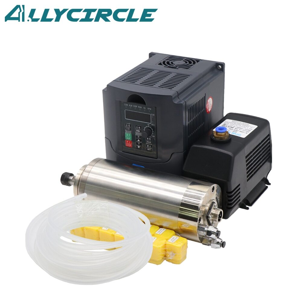
Buy a documented, matched VFD and spindle package for your mains supply. Check input phase and voltage, spindle voltage/current/frequency, cooling, and mounting; 1.5 kW alone is not a compatibility specification.
Add a PWM-to-0-10V converter module (~$10) to interface with GRBL cleanly.
Budget the complete installation, including a matched drive and spindle, cooling where required, cabling, control interface, and suitable enclosure.
Parts for this guide
If you are buying after reading this, these are the specs to look for.
| Part | What to buy | Where to look |
|---|---|---|
| Powered PWM to analog spindle interface GRBL's 5 V PWM cannot drive a 0 to 10 V VFD input without one. | Input compatible with classic GRBL's 5 V PWM amplitude and configured PWM frequency; powered 0 to 10 V output matched to VFD input impedance, with suitable isolation and a separate run/stop output. | |
| Matched VFD and spindle package Input must match your mains and output must match the spindle before any parameter is set. | For a 230 V mains build: VFD explicitly rated for single-phase 220 to 240 V input and three-phase spindle output, with continuous output current at least the selected spindle's nameplate current; match spindle voltage and approved maximum frequency. | |
| VFD spindle cable Replacing generic wiring with the correct motor cable completes the drive-to-spindle connection. | Flexible shielded VFD-rated cable with three phase conductors plus a protective-earth conductor, rated for the drive output and installation; size conductors to spindle current and fit the actual spindle connector and shield termination. |
"Search" buttons open a search for that exact spec, so compare listings against it before buying. Some links earn us a commission at no extra cost to you (disclosure).